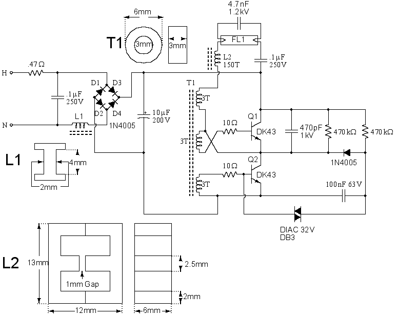
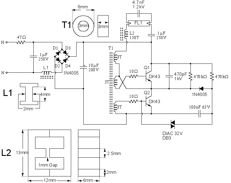
This circuit came from a 14 Watt Commercial Electric spiral bulb from Home Depot. It is very similar to a 16 Watt circuit on repairfaq.org. In fact, I drew it in that way because it was layed out very well, so much credit should go to Sam Goldwasser.
As the power comes in, it is filtered by L1 and a .1uF capacitor. A .47 Ohm reisitor is also provided and is probably fusible. It is then rectified by the bridge formed by D1-D4 and filtered by a 10uF capacitor. As power is first applied, a 100nF 63V capacitor begins charging through a 470k reisitor. Once this capacitor reaches 32V, the DIAC breaks over turning on Q2. Power then flows through Q2, the top winding of T1, L2, a filament of fluorescent bulb FL1, a 4.7nF capacitor, the other filament of FL1, and a .1uF capacitor, current being limited by L2 and the resistance in the filaments. Transformer action also begins inducing power in the other 2 windings of T1. This tends to begin to turn on Q1 and turn off Q2. Once Q1 is on, the charge that has built up in the .1uF and 4.7nF capacitors attached to FL1 begins flowing back the other way through the filaments, L2, the top turn of T1 and Q1. This once again induces power into the other two windings of T1 except in the opposite direction, eventually turning off Q1 and turning on Q2. The 470pF capacitor and other 470k resistor apparently make sure that both transistors are not on at the same time. Otherwise, it would be a dead short! Once the arc starts, most of the current flows directly between the filaments instead of through them. Only a small amount flows through them to keep them warm.
Read More Source:
http://silenceisdefeat.org/~lgtngstk/Sites/tls.html
http://www.elecfree.com/electronic/14-watt-compact-fluorescent-electronic-ballast/


