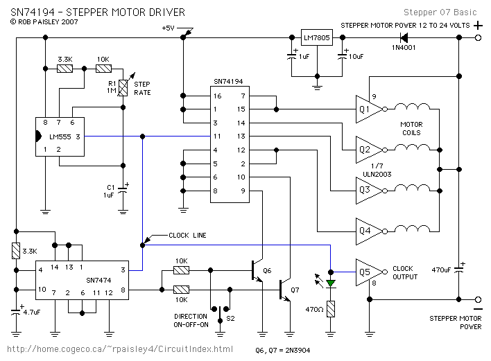
The following diagram is for the main circuit of the motor driver. A testing version is shown later on this page. The testing circuit is laid out differently and shows the SN7474 in logic block form and LED’s are used to indicate the motor coils being switched.
#The 555 astable oscillator produces a series of CLOCK pulses that are fed to PIN 11 of the SN74194 integrated circuit.
#Each time the CLOCK pulse goes HIGH (positive) the HIGH state at the SN74194’s OUTPUT terminals, (PIN’s 12, 13, 14, 15), is shifted either UP or DOWN y one place. Refer to the “Stepper Motor Driver Waveforms” diagram.
The direction of this shifting is controlled by switch S2. When S2 is in the center OFF position the HIGH output state will remain in its last position and the motor will be stopped.
When the base of Q6 is LOW the shifting will be PIN 12 - 15 - 14 - 13 - 12 .etc.
When the base of Q7 is LOW the shifting will be PIN 12 - 13 - 14 - 15 - 12 .etc.
The direction of the pulse shifting determines the direction of motor rotation.
#The pulses from the OUTPUT’s of the SN74194 are fed to four segments of the ULN2003 Driver. When the input of a segment is HIGH, its darlington transistor will turn ON and its OUTPUT will conduct current through one of the motors coils.
#As the coils of the motor are turned ON in sequence the motor rotates to follow these steps. Refer to following diagrams
Read More Source:
http://home.cogeco.ca/~rpaisley4/Stepper.html
http://www.elecfree.com/electronic/basic-stepper-motor-driver-by-74194/